
MIM is a brand-new metal parts near net molding processing technology formed by introducing modern plastic injection molding technology into the powder metallurgy field, which is a high-tech technology that has been carried out very rapidly in the powder metallurgy discipline and industrial field in recent years.
One of the newest metal processing technologies, MIM (Metal Injection Molding) was created by combining traditional plastic injection molding technology with powder metallurgy (PM) technology. Using metal molds for injection molding makes it easy to manufacture otherwise difficult parts, including miniature, precision, complex shapes and three-dimensional parts.MIM is also ideally suited for mass production, with our ability to produce 5,000 to 1 million parts per month.MIM is best suited for parts weighing between 0.05g and 50g, but it can also be used to mass produce parts weighing up to about 400g.

Powder Metal Injection Molding Process
Metal Injection Molding (MIM) is a process in which powdered metal is mixed and placed into a mold to create solid parts and devices. The mixture of powdered metal and bonding material (called feedstock) is available in limited quantities, making MIM ideal for making small, delicate parts. Areas of application for this process include machine parts, dental tools and firearms equipment, all of which typically involve small and complex metal parts.
Powder metallurgy technology determines which types of metals can be made into powders for the metal injection molding process. There are various methods of making metal powders, such as physical deposition, grinding, atomization, chemical reaction or centrifugal separation. The type of powder strategy depends greatly on the type of metal to be powdered and its specific quality.
Once the metal powder is produced it is mixed with a binder, which is a material consisting of various waxes and plastics. The blended mixture is known as the feedstock and is ready to be injected into the mold. Since the feedstock is similar to the molten plastic used in normal injection molding, the same injection molding equipment can be used for metal injection molding. The feedstock is injected into the injection molding equipment in small amounts, called injection molding, and then cooled in the mold.
Once the cooling is complete, some of the bonding material is removed from the part, usually by a solvent or chemical reaction, but sometimes the part is heated to melt the adhesive. At this point, the part contains a significant portion of voids, about 2% to 4% of the total volume, a stage known as the "browning stage." The metal is then made stronger and denser by the sintering process. During sintering, the metal is heated to a temperature slightly below its melting point until the surfaces of the metal particles are fused together, while still maintaining the structural integrity of the part. The result is a metal part with a solid density of up to 99%.
With minor modifications, the part is complete and ready for use. Because metal injection molding requires the use of a mold, it is a much more flexible technology and ideal for complex, delicate parts. Other metal technologies often require high costs to produce the same products, so metal injection molding is becoming an increasingly popular technology for manufacturing these parts.
Computer simulation of the injection molding process is advanced and allows the study of every detail of mold filling in 3D.
The design engineer can analyse the filling dynamics in thick and thin areas on screen, study the effects of gate position, thermal gradients in the mold and phenomena such as jetting and binder segregation.
Designers can also optimise the kinetics of mold filling and determine shrinkage and distortion of the green compact relative to the mold dimensions.
A careful analysis and optimisation of the mold cavities can reduce design time and cost while significantly improving yield and quality.
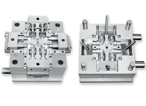
Figures1
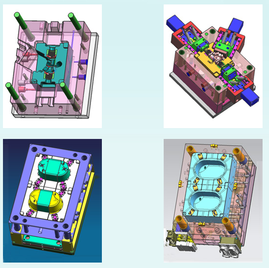
Figures2
"The Design Should Considerations"

--Metal Part must be so designed to allow for easy ejection from the die. Sidewalls should be perpendicular; hole axes should be parallel to the direction of opening and closing of the die.
--Holes, even complicated profiles, are permissible in the direction of compressing. The minimum hole diameter is 1.5 mm (0.060 in).
--The wall thickness should be compatible with the process typically 1.5 mm (0.060 in) minimum. Length to thickness ratio can be up to 18 maximum-this is to ensure that tooling is robust. However, wall thicknesses do not have to be uniform, unlike other processes, which offers the designer a great amount of flexibility in designing the parts.
--Undercuts are not acceptable, so designs have to be modified to work around this limitation. Threads for screws cannot be made and have to be machined later.
--Drafts are usually not desirable except for recesses formed by a punch making a blind hole. In such a case a 2-degree draft is recommended. Note that the requirement of no draft is more relaxed compared to other forming processes such as casting, molding etc.
--Tolerances are 0.3 % on dimensions. If repressing is done, the tolerances can be as good as 0.1 %. Repressing, however, increases the cost of the product.
"Designing New MIM Products and Solutions"
We know that timeliness is critical. Designing new products and solutions from scratch is all very well, but the designs need to be proven in real world situations. And they need to be proven fast. That’s where Harber Mmetal’s capabilities are truly world class, and where we continue to invest in our service. We work with our customers at the earliest stages of the design cycle. From an initial concept we can prototype new designs at incredible speed – sometimes even within 24-hours – thanks to our highly skilled design engineers and harnessing our expertise.
Commonly used materials for MIM process and their application fields:
| Material system | Alloy model | Application filed |
| Low alloy system | Fe2Ni, Fe8Ni | Structural parts in automobile, mechanical industries etc. |
| Stainless steel | 316L, 304, 17-4PH, 420, 440C | Medical devices, watch |
| Hard alloy | WC-Co | Various kinds of cutting tools, watches |
| Heavy alloy | W-Ni-Fe, W-Ni-Cu, W-Cu | Military, tele-communication |
| Titanium alloy | Ti, Ti6Al4V | Medical devices, military structural parts |
| Tool steel | CrMo4, M2 | All kind of tools |
The performance of several typical materials:
| Material | Density | Hardness | Tensile strength | Elongation | |
| g/cm³ | Rockwell | Mpa | % | ||
| Iron base alloy | PIM-2200(sintering state) | 7.65 | 45HRB | 290 | 40 |
| PIM-2700(sintering state) | 7.65 | 69HRB | 440 | 26 | |
| PIM-4605(sintering state) | 7.62 | 62HRB | 415 | 15 | |
| PIM-4605(quenching, tempering) | 7.62 | 68HRB | 1655 | 2 | |
| Stainless steel | PIM-316L(sintering state) | 7.92 | 67HB | 520 | 50 |
| PIM-17-4PH(sintering state) | 7.50 | 27HRC | 900 | 6 | |
| PIM-17-4PH(sintering state) | 7.50 | 40HRC | 1185 | 6 | |
| PIM-430L | 7.50 | 65HRC | 415 | 25 | |
| Tungsten alloy | 95%W-Ni-Fe | 18.1 | 30 | 960 | 25 |
| 97%W-Ni-Fe | 18.5 | 30 | 940 | 15 | |
Forming ability comparison of MIM and precision casting:
| Feature | Precision casting | MIM |
| Min hole diameter | 2mm | 0.4mm |
| Max depth for 2mm blind hole | 2mm | 20mm |
| Min wall thickness | 2mm | 0.3mm |
| Max wall thickness | No limit | 10mm |
| Tolerance for 4mm diameter | ±0.2mm | ±0.04 |
| Surface roughness(Ra) | 5μm | 1μm |
Comprehensive comparison of MIM and other processes:
| Process Content | MIM | PM | Precision casting | CNC machining |
| Density | 90% | 86% | 98% | 100% |
| Tensile strength | high | Low | High | High |
| Finish | high | middle | Middle | high |
| Miniaturization capability | high | middle | Low | Middle |
| Thin all capability | high | middle | middle | Low |
| Complexity | high | Low | middle | High |
| Tolerance of design | high | Middle | middle | Middle |
| Material range | high | high | middle | high |
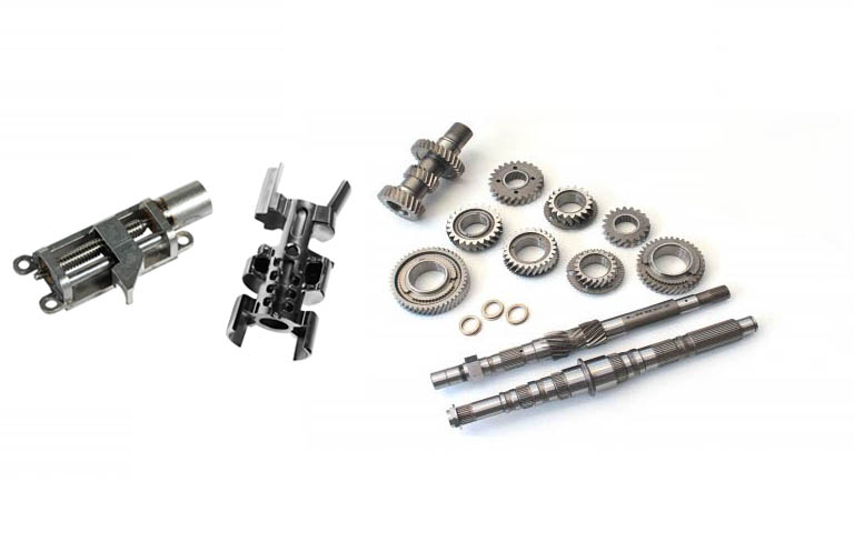
Application of Metal MIM Parts
Metal powder injection molding has been widely used in mechanical industry, electronic industry, automobile industry, office automatic industry, watch, photoelectric industry, military industry, medical devices etc.
1) Computers and auxiliary facilities: printer parts, core, striker shaft pin, drive parts
2)Tools: such as gun drill, drill chuck, power tools, hand tools, wrenches and other spare parts, milling heads, nozzles, etc.
3) Household appliances: such as watch case, bracelet, electric toothbrushes, scissors, fans, golf head,
simulation jewelry, tool heads and other parts;
4) Medical equipment parts: dental orthopedic frame, orthopedic bracing parts, scissors, tweezers;
5) Military ordnance parts: the missile tail, firearms parts, warheads, liner, Fuze parts;
6) Electrical parts: such as micro-motor parts, electronic parts, sensors, cell phones etc.
7) Mechanical Parts: complex parts such as small loose cotton, textile machines, sewing machines.
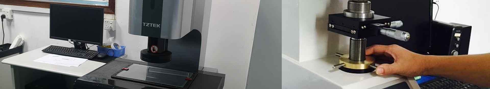
Technical Assistance
The metal injection machining process begins with experienced design engineers reviewing a part’s dimensions per customer drawing and then creating an AutoCAD rendition of the measurements in preparation for tooling. Our design engineer determines how many parts and offers suggestions of how the part can be manufactured with the lowest tolerances within our machining capabilities.
If your business is in need of a high quality and cost-effective metal injection molding service, then Harber Metal have the solution to your problem.