
 Deutsch
  Japanese
  English
  Korean
  français
  español
  русский
  português
  Italia
Precision Mechanical Components for High-Performance Tools: Process, Materials, Applications and MIM Relationship
Precision mechanical components are the small, complex, high-tolerance metal parts that make high-performance tools work — gears, cams, latches, pawls, housings, brackets, fasteners and sliding mechanisms in power tools, hand tools, lock systems, surgical instruments and industrial equipment. These parts must combine dimensional accuracy, strength, wear resistance and repeatable batch quality, which is exactly the window where Metal Injection Molding (MIM) is most valuable.
Like the broader powder injection molding family, MIM uses feedstock preparation, injection molding, debinding and sintering, but the final material behavior is metal — giving strength, toughness, hardenability and conductivity. MIM is worth reviewing when a tool component needs small complex geometry, controlled strength and wear performance, and the shape would be costly to machine or forge. It should be avoided or redesigned when a component is too large, too flat, too low in volume, or relies on properties MIM cannot cost-effectively deliver. This page helps engineers decide whether a precision tool-component drawing should enter MIM feasibility review.
Quick Engineering Summary
Use MIM When
The tool component is small, complex, produced in repeatable volume, and needs strength, wear resistance or hardenability that would be expensive to achieve by machining or forging.
Review Carefully When
Review thin walls, sharp internal corners, deep holes, gate position, sintering support, tight tolerances, heat-treatment distortion and functional contact surfaces before tooling.
Avoid Direct Substitution
Do not convert a CNC-machined or forged tool part to MIM by changing material alone. Recheck wall balance, load path, heat-treatment response, corrosion protection and finishing requirements.
Is Your Part a MIM Candidate?
Before a precision tool component enters tooling review, the project team should confirm whether the required function, geometry, tolerance strategy, finishing needs, inspection method and annual volume fit Metal Injection Molding. This table is an early screening tool, not a final manufacturability decision.
| Review Item | Good MIM Candidate Signal | Risk Signal Requiring Redesign or Another Route |
|---|---|---|
| Material function | The part needs metal strength, toughness, wear resistance, hardenability or conductivity. | The part needs large size, extreme flatness, or properties outside the MIM window. |
| Geometry | The part has small complex metal features — teeth, cams, slots, bosses, internal profiles or undercuts costly to machine. | The design has very long unsupported features, extremely thin lips, sharp internal corners, or wall transitions that cannot be modified. |
| Tolerance strategy | Critical dimensions can be clearly defined, and non-critical dimensions remain within practical as-sintered capability. | Nearly every dimension is extremely tight, but there is no allowance for post-sinter machining or detailed inspection planning. |
| Finishing requirement | Only functional surfaces, sealing areas or selected datums need post-sintering finishing. | Large-area precision finishing is required across many surfaces, increasing cost and lead time. |
| Assembly condition | The part is assembled under controlled loading consistent with MIM dimensional stability. | The part is pressed, tightened, impacted or flexed in a way that assumes continuous wrought-steel behavior. |
| Production volume | The annual quantity can justify tooling, feedstock validation, debinding, sintering, heat treatment and inspection development. | The project is one-off or very low volume, making CNC machining or prototyping more practical for early validation. |
What Are Precision Mechanical Components for High-Performance Tools?
Precision mechanical components are the functional metal parts inside tools that convert force, motion, locking, indexing or actuation into reliable operation. In a high-performance tool, these components are typically small, carry concentrated load, slide or rotate against mating parts, and must hold tight dimensional relationships batch after batch.
MIM is considered when such a component is too small, complex or costly to manufacture efficiently by conventional machining, forging or stamping. It is especially relevant for parts with thin walls, small holes, curved shapes, miniature features, repeated production demand, or functional surfaces that would be expensive to machine from a solid bar or blank.
Metal Powder and Binder Feedstock
Metal powder is compounded with a binder to create feedstock with controlled flow behavior. Feedstock quality affects molding, debinding, sintering, density and final hardenability.
Molding and Green-Part Handling
The feedstock is injected into a precision mold cavity to form a green metal part. Fragile features, thin sections and ejection surfaces must be reviewed early.
Debinding, Sintering and Heat Treatment
After molding, binder removal, sintering and (for hardenable grades) heat treatment determine density, strength, hardness, dimensional stability and distortion risk.
MIM should not be treated as "plastic injection molding with metal powder." The molded shape is only the intermediate state. Final quality depends on powder characteristics, binder removal, sintering control, geometry robustness, support strategy, edge design, heat-treatment response, finishing allowance and inspection requirements.
How MIM Relates to Traditional Tool-Component Manufacturing
MIM belongs to the broader Powder Injection Molding family and is one route among several for producing precision tool components. Traditional routes include CNC machining (subtractive), forging, stamping and conventional press-and-sinter PM. MIM differs by forming complex near-net-shape metal geometry in one molding step.
The relationship is real, but the engineering judgment is different. MIM and CNC machining may produce similar-looking components, but a sintered MIM part has residual micro-porosity, controlled shrinkage and heat-treatment behavior that must be evaluated differently from a fully dense machined or forged part.
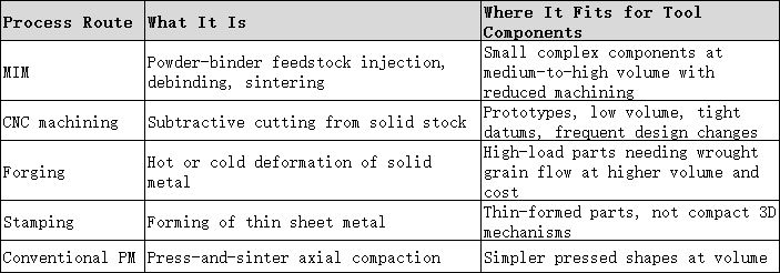
A common mistake is assuming that because a tool component works as a machined or forged part, the same design can be copied directly into MIM. That is not safe. A machined design often contains features easy to cut but risky to mold and sinter — sharp corners, unbalanced walls, deep slots and aggressive ribs. When converting to MIM, review wall balance, datums, holes, ribs, bosses, gate position and heat-treatment distortion instead of copying the drawing directly.
MIM Process Flow for Precision Tool Components
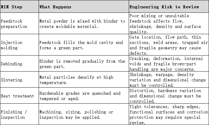
A useful way to understand MIM for tool components is to separate molding success from final part success. A molded green part can look acceptable, but cracking, warpage, shrinkage variation, density problems or edge damage may appear later during debinding, sintering, heat treatment, finishing or assembly.
Feedstock Preparation
MIM feedstock must balance metal-powder loading and binder flow behavior. If the feedstock does not fill the cavity consistently, molding defects may appear. If the binder system or powder distribution is not suitable, the part may still fail during debinding or sintering. Feedstock behavior matters when the part has thin walls, long flow paths, micro-features, small holes or large wall-thickness transitions.
Injection Molding
The molding stage determines the green-part geometry. Gate location, cavity filling, venting, flow balance, weld areas and ejection must be reviewed early. For high-performance tool components with precise teeth, cams or slots, fragile features and sharp transitions require extra caution because damage can propagate through later stages.
Debinding
Debinding removes the binder from the molded part. This is one of the most sensitive points in MIM. If binder removal is too aggressive or the geometry creates uneven removal paths, the part may crack, deform or develop internal defects. Debinding risk is especially important when a component has thick and thin sections in the same part, closed pockets, very small channels or delicate unsupported features.
Sintering
Sintering develops the final metal body. During sintering, the part shrinks and densifies. Shrinkage control, density uniformity and support strategy directly affect whether critical teeth, hole positions and flatness stay within tolerance.
Heat Treatment
For hardenable grades such as 17-4PH, 4140, 420 or 440C, heat treatment develops the final hardness and wear resistance. Heat-treatment distortion must be reviewed against critical dimensions, and hardness must be verified by sampling.
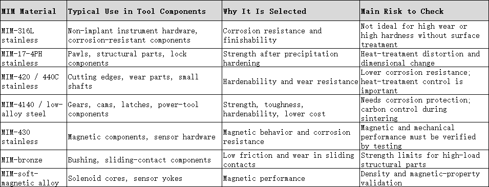
Common MIM Materials for High-Performance Tool Components
Material selection should start from the component's failure mode and load condition, not from industry habit. A gear, cam, latch, pawl and housing each need different material balance.
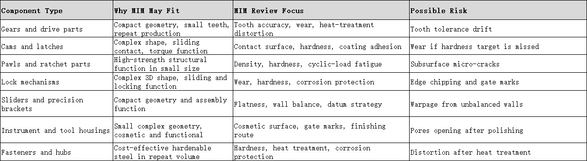
Suitable Precision Component Types
The best MIM tool components are usually not simple blocks or large housings. They are small components where material performance, shape complexity and repeat volume all matter.
Limitations and Design Risks of MIM Tool Components
A part may appear suitable because it is small and complex, but MIM material behavior — residual porosity, shrinkage and heat-treatment response — can make the design risky. Before tooling, the key question is whether the geometry can survive debinding, sintering, heat treatment, handling, finishing, inspection, assembly and service loading.
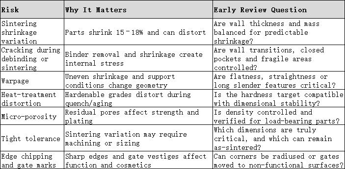
The risk is not only whether a crack appears during production; it is also whether small flaws, sharp edges or local stress can create later failures during assembly or service.
Representative Engineering Scenario: Unbalanced Pawl Geometry
Scenario disclosure: The following is a representative engineering example used to explain common MIM design and process risks. It is not a specific customer project, production record or verified field case.
What problem occurred: A small 17-4PH pawl component looked suitable for MIM, but trial parts showed warpage and occasional subsurface cracking after heat treatment.
Why it happened: The geometry combined a sharp inner corner, a heavy hub and an abrupt wall transition. The green part could be molded, but sintering and heat treatment created stress around the transition area.
What the real system cause was: The failure was a combined design, sintering, support and heat-treatment issue. The geometry did not provide enough structural robustness for the heat-treatment response.
How it was corrected: The sharp corner was given a controlled radius, the wall transition was balanced, and the heat-treatment cycle was recalibrated with density and hardness validation.
How to prevent recurrence: Before tooling, review wall transitions, local mass, gate position, sintering support, critical dimensions and heat-treatment distortion. Do not judge MIM suitability only by mold filling.
As-Sintered vs Finished Features in MIM Tool Components
MIM is a near-net-shape process, but near-net-shape does not mean every feature is ready for final assembly without finishing. Critical functional surfaces should be separated from non-critical surfaces early so tolerance, finishing, inspection and cost expectations remain realistic.
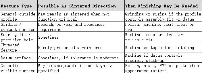
For RFQ review, mark which surfaces are functional, sliding, sealing, datum-related, cosmetic or non-critical. This prevents the whole part from being treated as a fully precision-machined component when only selected features require tight control.
MIM vs CNC vs Forging: Selection Logic
MIM and other routes should be compared when the part is small, complex and suitable for powder injection molding geometry, but the required production volume and tolerance strategy are still uncertain. The practical selection question is simple: does the component need repeat production of complex small metal geometry?
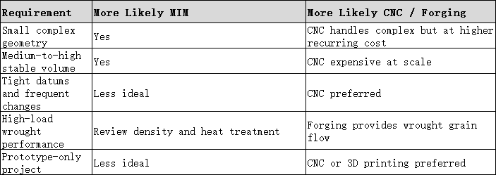
This section is a selection overview. For a full route-by-route comparison of material behavior, cost drivers, tolerance strategy, geometry suitability and project decision logic, review the MIM vs CNC guide.
When MIM May Not Be the Right Manufacturing Route
MIM is not the best route for every precision tool component. In some projects, CNC machining, forging, conventional PM, stamping or another route may be more practical.
The project volume is too low to justify tooling and feedstock/process development.
The part shape is simple enough for pressing or machining.
The part is very large or very flat, where sintering distortion becomes difficult to control.
The part has sharp internal corners, very thin lips or extreme wall variation that cannot be modified.
Nearly every dimension is tight with no allowance for machining, sizing or detailed inspection.
The drawing keeps changing, so flexible machining is more appropriate.
The design needs mirror-cosmetic surfaces without finishing allowance.
Representative Engineering Scenario: Machined Part Converted Without Wall Review
Scenario disclosure: The following is a representative engineering example used to explain common MIM design and process-selection risks. It is not a specific customer project, production record or verified field case.
What problem occurred: A project team considered converting a CNC-machined tool bracket to MIM for cost savings.
Why it happened: The team focused on cost reduction but did not review wall balance or sintering support. The original machined design had a heavy hub connected to a thin wall.
What the real system cause was: The original geometry depended on machining freedom, not molding stability. A MIM part with that unbalanced wall structure would warp during sintering.
How it was corrected: The design was reviewed for wall balance, support surfaces, gate location and local mass. The team redesigned the transition rather than copying the machined drawing.
How to prevent recurrence: Do not convert machined parts to MIM only by changing material. Review wall balance, datums, gate position, sintering support and finishing route before tooling.
China Custom Metal Injection Molding manufacturer Harbermetal
Many engineers design a precision tool component as a machined part, then try to convert it to MIM by changing the material alone — and discover after tooling that unbalanced walls, gate marks on functional surfaces or heat-treatment distortion push every fix onto your schedule. You don't need to learn these lessons through expensive trial-and-error. Send your 2D/3D drawings, material requirements, hardness target and volume forecast to Harbermetal. Our engineering team runs a drawing-based material and DFM review — confirming wall balance, gate position, sintering support, heat-treatment response, corrosion-protection plan and dimensional strategy — before you invest in any tooling.
Harbermetal is an ISO-certified full-chain China custom MIM manufacturer — a real manufacturer, not a trading intermediary. We complete the whole MIM route in-house: feedstock evaluation, custom mold development, metal injection molding, multi-stage debinding, controlled-atmosphere / vacuum sintering, dedicated heat treatment, secondary CNC sizing and diversified surface finishing (tumbling, passivation, electropolishing, plating and coating coordination).
Our engineering team reviews every incoming drawing against material suitability, geometry risk, wall balance, gate location, sintering support, heat-treatment response, tolerance strategy and finishing route. We produce custom precision MIM components in stainless steels (304L, 316L, 17-4PH, 420, 440C), low-alloy steels (4140, 8620 directions), bronze, soft-magnetic alloys, titanium and nickel-base alloys for power-tool, lock-system, automotive, consumer-electronics, wearable and non-implant medical-instrument hardware. We provide first-article inspection reports, density/hardness/metallographic test records and full batch-traceability documentation from prototype validation to high-volume serial production.
What Information Should Be Prepared for a MIM Process Review?
A MIM review becomes useful when the project team has enough information to evaluate material behavior, geometry, tolerance, production volume and process risk. A general part description is not enough; the review should connect the drawing, functional requirement, manufacturing route, inspection plan and expected production quantity.
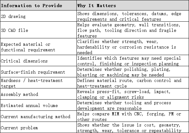
A good early review does not simply ask, "Can this be molded?" It asks whether the part can be molded, debound, sintered, heat-treated, finished, inspected, assembled and used reliably.
Request a MIM Process Review for Your Precision Tool Component
If your component requires small complex geometry and you are comparing MIM, CNC, forging, PM or another route, send the project details for an early process-suitability review.
Please provide 2D drawings, 3D CAD files, expected material behavior, critical dimensions, surface-finish requirements, hardness and heat-treatment targets, application environment, assembly method, estimated annual volume and the current manufacturing issue. Harbermetal's engineering team will confirm whether the part is better suited to MIM or another route and identify early risks related to material selection, shrinkage, tolerance, heat treatment, tooling, finishing and inspection before tooling investment.
Contact information
Email: sales@harber-mim.com
Tel: +86 0769-82389116
FAQ: Precision Mechanical Components for High-Performance Tools
What types of precision components are made by MIM for high-performance tools?
Common MIM tool components include gears, cams, latches, pawls, lock mechanisms, sliders, precision brackets, small shafts, fasteners and instrument housings — small complex metal parts that need strength, wear resistance and repeatable batch quality.
Why use MIM for precision tool components?
MIM forms complex near-net-shape metal geometry in one molding step, reducing machining and material waste for small parts at medium-to-high volume. It suits components with teeth, cams, slots, bosses, internal profiles or undercuts that would be expensive to machine.
Can MIM design rules be used directly from CNC-machined parts?
No. A machined design often contains features easy to cut but risky to mold and sinter. When converting to MIM, review wall balance, datums, holes, ribs, bosses, gate position and heat-treatment distortion instead of copying the drawing directly.
What materials are used for MIM tool components?
Common materials include 316L, 17-4PH, 420 and 440C stainless steels, low-alloy steels such as 4140, bronze and soft-magnetic alloys, depending on strength, wear, hardenability, corrosion and magnetic requirements.
Do MIM tool components need post-sinter machining?
Some can be used as-sintered, but critical holes, bearing fits, sliding surfaces, threads, precision datums and cosmetic surfaces often need post-sinter machining, sizing, polishing or heat treatment.
Is MIM suitable for low-volume tool-component projects?
MIM is usually more suitable when production volume can justify tooling and process development. For very low-volume projects, CNC machining or prototyping may be more practical.
Should I choose MIM or CNC for my precision tool component?
Choose MIM when the component is small, complex and produced in stable medium-to-high volume. Choose CNC for prototypes, low volume, tight datums and frequent design changes.
What should I prepare before requesting a MIM review?
Prepare a 2D drawing, 3D CAD file, material or functional requirements, critical dimensions, hardness and heat-treatment targets, surface-finish requirements, assembly method, estimated annual volume, current manufacturing method and the main problem you want to solve.
Ready to evaluate MIM for your precision tool component?
Submit your drawings and functional specifications for a free material and DFM review and transparent quotation.
Request A Free Quote