
 Deutsch
 Japanese
 English
 Korean
 français
 español
 русский
 português
 Italia

What Sand Casting Actually Is
Sand casting is a metal casting process in which molten metal is poured into a cavity formed in compacted sand, allowed to solidify, and then released by breaking the mold apart.
The economics follow directly from that: the mold is expendable, so the pattern is the only tooling. One pattern can produce thousands of molds. That is why sand casting tooling costs a fraction of die casting, and why it is the default route for large, geometrically complex parts produced in low to medium volumes.
The trade-offs are equally direct:
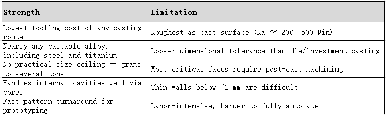
This guide covers the process step by step, the sand systems and when each wins, material selection, tolerance and machining stock, defect control, real cost drivers, and how sand casting compares with die casting, investment casting and metal injection molding.
Key Takeaways
Seven process steps: pattern → mold (cope/drag + gating + risers) → cores → melt and pour → solidify and cool → shakeout → finishing and inspection.
Green sand is the cheapest system (silica + bentonite clay + water). Resin/no-bake, shell and sodium silicate systems cost more but hold dimensions better and suit larger or more demanding castings.
Defects are mostly formed in mold-making and pouring, not in finishing — sand inclusion, burn-on, veining, gas porosity and shrinkage porosity are all controlled by compaction quality, coating, sand grain and pouring temperature.
Alloy range is nearly universal: gray and ductile iron, carbon and alloy steel, aluminum, copper alloys, bronze, nickel and titanium.
Tolerance is loose. The classic rule of thumb is ±0.020 in/in (≈ ±0.5 mm per 25 mm), best formalized by ISO 8062 dimensional casting tolerance grades (typically DCTG 5–8 for sand casting).
Plan machining stock from day one on bearing bores, sealing faces and mounting surfaces — but not on cosmetic faces.
Cost is driven by four factors: tooling, alloy, volume and finishing/inspection. Tooling is low; machining and NDT raise cost.
Sand casting loses to MIM, die casting and investment casting on thin walls, fine detail and tight tolerance — but wins on size, alloy freedom and tooling economy.
1. The Seven Steps of Sand Casting
Understanding where defects originate requires mapping each defect to the step that caused it. Foseco's defect taxonomy maps cleanly onto this sequence.
Step 1 — Pattern making
A pattern is a replica of the part, made from wood, foam, metal, resin or a 3D print. It forms the cavity in the sand.
Critical design rule: the pattern must include draft (taper) and machining allowance. A pattern without draft tears the mold during withdrawal; a pattern without machining allowance leaves critical faces undersized.
For prototypes and one-off parts, a 3D-printed or foam pattern eliminates pattern-making lead time entirely. Once the design is stable, convert to a durable wood, resin or metal pattern for repeat production.
Step 2 — Mold making (cope and drag)
The mold is split into two halves: the cope (top) and the drag (bottom). Sand is packed around the pattern in each half, then the pattern is withdrawn.
At the same time, the gating system is cut in:
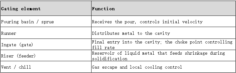
What goes wrong here: loose or uneven sand packing lets sand grains wash into the metal stream, producing sand inclusion. Poor gating design causes turbulence, entrained air and oxide films.
Step 3 — Core setting
Cores are separate sand shapes that occupy space where internal cavities or undercuts must exist — water jackets, oil galleries, cooling passages.
What goes wrong here: a shifted or poorly supported core distorts wall thickness; a core that traps gas creates internal porosity exactly where it cannot be seen.
Step 4 — Melting and pouring
The alloy is melted to the specified composition and superheat, then poured into the cavity.
What goes wrong here:
Burn-on — hot metal penetrates the sand surface and fuses with it, requiring heavy cleaning or chipping.
Veining — thermal cracking of the mold face lets metal flow into the cracks, forming thin fins on the casting surface.
Scabbing / spalling — a section of mold face breaks away and is embedded in the casting.
Cold shut / misrun — metal freezes before the cavity fills, usually from insufficient superheat or too slow a pour.
Step 5 — Solidification and cooling
Metal solidifies in the mold. Shrinkage is inevitable — most alloys contract roughly 3–7% volumetrically between liquid and solid, and further on cooling to room temperature.
Risers must remain liquid long enough to feed the shrinking casting. The governing relationship is Chvorinov's rule: solidification time is proportional to (Volume / Surface Area)². A riser must therefore have a larger modulus than the section it feeds:
Solidification time t ≈ B × (V/A)ⁿ, where n ≈ 2 and B is a mold constant.
What goes wrong here: uneven cooling produces shrinkage porosity — internal voids in the last-to-solidify sections, often at thick-section junctions and away from risers.
Step 6 — Shakeout
The mold is broken apart and the sand is recovered and recycled (with makeup sand and rebonding).
What goes wrong here: removing the casting too early — while still hot and weak — causes warping and cracking.
Step 7 — Finishing and inspection
Gates and risers are cut off, then the part is ground, heat-treated, machined and inspected.
What goes wrong here: skipping or shortcutting inspection hides porosity until the part fails in service. The lesson is straightforward: inspection is not a final cosmetic step, it is the last chance to reject hidden internal defects.
Where quality is actually won: steps 2 to 4. Mold compaction, gating design and pouring control determine casting quality far more than finishing operations can repair.
2. Which Sand System Should You Choose?
The correct sand system is set by part weight, surface requirement, dimensional tolerance and production method — not by sand price alone.

Why "green" doesn't mean environmentally green
The name refers to the mold being uncured (still moist), not to environmental performance. Green sand is the traditional clay-bonded system.
On size limits — the sources are not actually contradictory
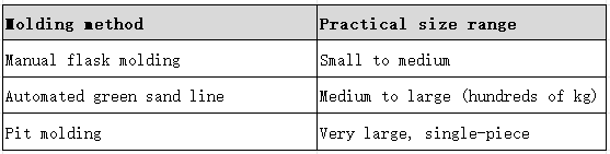
Published claims range from "green sand suits castings under 50 kg" to "automated green sand lines handle up to 500 kg" to "pit molding produces very large iron castings in green sand."
All three can be true simultaneously, because the limit is set by the molding method, not by the sand:
Cost difference: resin versus green sand
Published patent data suggests resin-bonded sand molds cost roughly 15–20% more to produce than green sand molds. On a USD 1,000 green sand mold cost, that implies roughly USD 1,150–1,200 for resin. Treat this as an indicative ratio from a patent filing, not a universal benchmark — actual cost depends on binder price, curing energy, reclamation rate and labor.
3. Materials: What You Can Cast
3.1 Molding sands
Sand selection is driven by pouring temperature and required surface quality. The refractory must survive the metal.
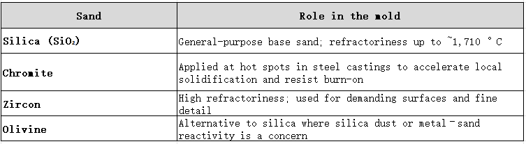
Practical strategy: use silica as the bulk sand, and switch to chromite or zircon only at critical zones — thick sections, hot spots, and surfaces where burn-on or veining cannot be tolerated. This captures most of the benefit at a fraction of the cost of an all-premium mold.
3.2 Binders
Bentonite clay is standard for green sand. Furan or phenolic resin dominates no-bake. Sodium silicate is the inorganic option. Binder choice affects dimensional stability, surface finish, sand reclamation and emissions — all four should be weighed, not just cost.
3.3 Cast alloys
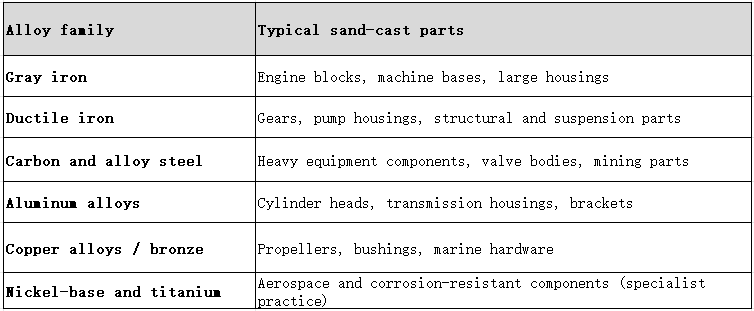
The alloy choice usually drives the sand choice, because pouring temperature sets the refractory requirement. Steel at ~1,550–1,600 °C demands far more from the mold face than aluminum at ~700 °C.
4. Sand Casting vs Die Casting vs Investment Casting
There is no universal "best" casting process — only the best fit for a given part.
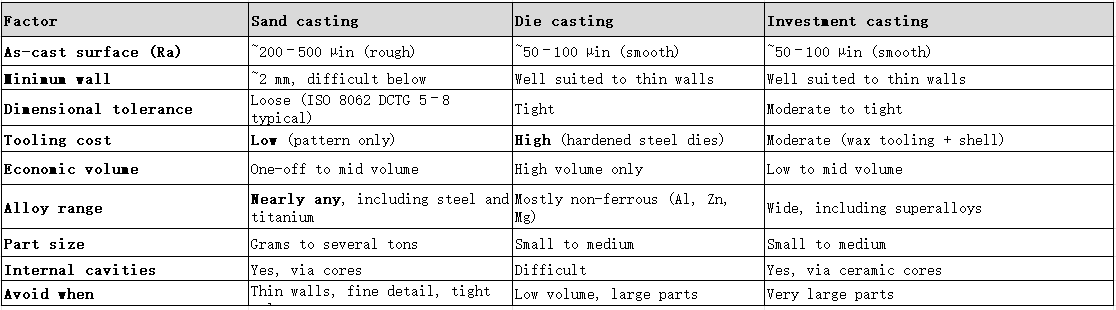
The surface-finish gap in perspective: sand-cast surfaces are roughly 2× to 10× rougher than die or investment cast surfaces depending on the sand and coating used. That range maps onto a real decision: a painted cosmetic surface can stay as-cast, while a sealing face or bearing bore must be machined regardless of process.
5. Tolerance Reality: How Accurate Is Sand Casting?
Sand casting is the least dimensionally precise of the common casting processes. Accept that up front and design around it.
The rule of thumb
±0.020 in/in (approximately ±0.5 mm per 25 mm) is the classic sand casting tolerance rule. Confirm the actual figure against your foundry's process capability — the rule is a starting assumption, not a guarantee.
What that means in practice
On a 150 mm (≈6 in) dimension:
±0.020 in/in × 6 in ≈ ±0.12 in ≈ ±3.0 mm
That is a large envelope. Two consequences follow:
Machining stock must be sized accordingly. On that face you need at least ~3 mm of stock plus allowance for surface roughness and skin defects — often 4–6 mm in practice.
Only functional faces need stock. Bearing bores, sealing faces, mounting pads and datum surfaces get stock. Cosmetic and non-functional surfaces should stay as-cast to avoid unnecessary machining cost.
The formal standard: ISO 8062
Instead of relying on a rule of thumb, specify ISO 8062-3 dimensional casting tolerance grades (DCTG):
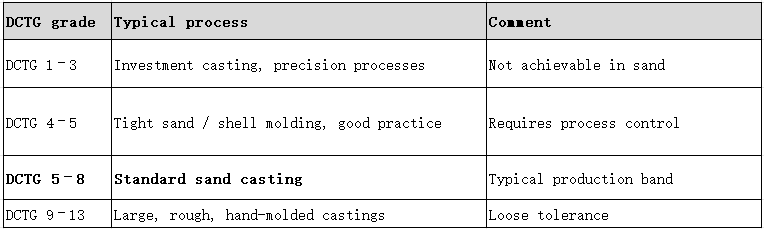
Naming an ISO 8062 grade in the RFQ removes ambiguity and prevents post-delivery arguments about what "normal tolerance" means.
A note on finer sand
Finer sand and better coatings can improve as-cast surface texture — but at a cost. Finer sand reduces mold permeability, which can trap gas and create porosity. Surface quality and internal soundness trade against each other; both must be specified.
6. Defect Catalogue and Prevention
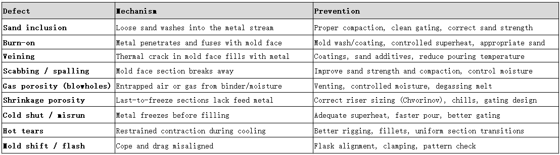
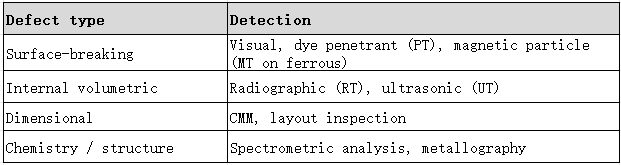
Detection methods by defect type:
7. What Drives Sand Casting Cost?
Cost breaks into four controllable buckets. Always request them quoted separately — bundled pricing hides the drivers.

The cheapest sand casting is the one you never machine. Every surface specified as-machined adds setup, cycle time and inspection cost. Define as-cast surfaces deliberately.
8. Applications: Where Sand Casting Genuinely Wins
Sand casting dominates where parts are large, internally complex, and needed in quantities too low to justify die tooling.
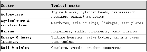
Automotive remains the anchor application because engine blocks and cylinder heads combine internal passages (formed by cores), mixed wall thickness, and iron or aluminum alloys — a combination no competing process handles as economically at that size.
A fast self-test for your own part
Ask four questions:
Is the part heavy or large (roughly >500 g and geometrically bulky)?
Does it need internal cavities?
Is the annual volume lower than a die-casting run would justify?
Is tolerance moderate (ISO 8062 DCTG 5–8 acceptable)?
If you answer yes to most, sand casting is a strong first candidate. If the part is small, thin-walled, high-precision and needed in five-figure annual volumes, a different process — including MIM — is usually the better route.
9. How to Choose a Sand Casting Foundry: RFQ Checklist
Most sourcing guides compare only price. Compare capability first, then price.
What to include in every RFQ
Drawing with tolerances and critical faces clearly marked
Material specification (e.g., an ASTM or GB grade, or ISO 8062 DCTG)
Annual quantity and quantity per order
Machining stock requirements and which faces are as-cast
Inspection and certification requirements (NDT level, material certificate, dimensional report)
Surface finish and coating requirements
What to ask the foundry
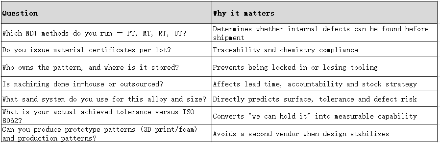
Pricing discipline: request separate line items for pattern, casting, machining, NDT and heat treatment. A single bundled number cannot be compared across foundries.
10. Sand Casting vs MIM: Two Different Ends of the Spectrum
Sand casting and metal injection molding are not competitors — they occupy opposite ends of the manufacturing spectrum, and confusing them is a common sourcing error.
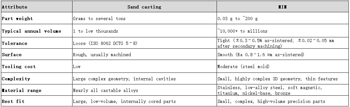
The decision rule is simple: if the part is small, geometrically intricate, and required in five-figure annual volumes with tight tolerance, sand casting will force you into heavy machining — and MIM will usually be cheaper and more repeatable. If the part is large or needed in dozens, sand casting is the only economic route.
For teams making that decision, the process comparison should be done at the drawing stage, before tooling, because the tooling investment differs by an order of magnitude.
Metal Injection Molding Partner for Complex, High-Volume Precision Parts
Harbermetal (Harber Industrial Limited) is an ISO-certified, full-chain metal injection molding manufacturer based in Chang'an Town, Dongguan, China, established in 2014. We exist for the part category that sand casting cannot serve economically: small, geometrically complex, high-precision metal components required in five-figure annual volumes.
Our in-house capability runs the entire MIM chain without subcontracting: feedstock evaluation → custom mold development → injection molding → multi-stage solvent-thermal debinding → vacuum/controlled-atmosphere sintering → heat treatment → secondary CNC sizing → surface finishing (tumbling, passivation, electropolishing, blasting, plating/PVD). We work with stainless steels (304L, 316L, 17-4PH, 420, 440C), low-alloy steels (4140/8620/4340 direction), bronze, soft magnetic Fe-Si and Fe-Ni alloys, titanium and nickel-base alloys such as Inconel 718/625.
What we can state verifiably: sintering shrinkage 15–18% is compensated in the mold design; as-sintered tolerance ±0.3–0.5%, tightened to ±0.02–0.05 mm by secondary CNC; relative density ≥95–96% (316L ≥7.5 g/cm³); process capability target Cpk ≥ 1.33; as-sintered surface Ra 0.8–1.6 µm, down to Ra 0.1–0.4 µm by electropolishing. Our QC laboratory runs CMM, density measurement, hardness testing, metallography, salt-spray and tensile testing, with carbon-sulfur analysis by LECO. Products comply with RoHS, REACH and PAHS; ISO 14001, IATF 16949 and ISO 13485 certifications are in progress. Two modern production bases, a 1,200 m² facility added in 2023 for small/complex/high-precision batch production, and a technical team of 30+ engineers support commercial kitchen hardware, consumer electronics, automotive hardware, security locks and non-implantable medical auxiliary parts.
Many engineers start a complex small metal part on sand casting or CNC simply because that is the process their existing supplier offers. They find out after tooling that the casting needs three machining operations to hold a tolerance it was never designed for — or that the CNC cycle time makes the unit price impossible at 50,000 pieces a year. You don't need to learn that lesson through an expensive tooling commitment.
Send your 2D/3D drawings, target annual volume, tolerance callouts and material specification to Harbermetal. We run a drawing-based DFM review before any mold is cut: wall thickness, draft, gate location, sintering support, shrinkage compensation, tolerance stack, and which features should be molded net-shape versus sized in secondary CNC. We will tell you honestly whether MIM is the right route for this part — or whether sand casting, CNC or another process will actually cost you less. That answer arrives before you spend money on tooling, not after.
Contact information
Email: service@harber-mim.com
Tel: +86 0769-82389116
Request A Free Quote
Frequently Asked Questions
What is the difference between green sand and resin sand casting?
Green sand uses bentonite clay and water as the binder and is the lowest-cost system, but it gives a rougher finish and looser dimensional control. Resin (no-bake, furan or phenolic) systems use chemical binders cured in the mold, providing better dimensional stability and surface quality — at roughly 15–20% higher mold production cost according to published patent data.
What are the main advantages and disadvantages of sand casting?
Advantages: lowest tooling cost of any casting route, an almost unrestricted alloy range including steel and titanium, no practical size limit, and the ability to form internal cavities with cores.
Disadvantages: the roughest as-cast surface, loose dimensional tolerance (typically ISO 8062 DCTG 5–8), thin walls below ~2 mm are difficult, and most critical faces require post-cast machining.
What drives sand casting cost?
Four factors: tooling/pattern, alloy, volume and finishing/inspection. Tooling is low because only a pattern is needed, which makes sand casting competitive at low to mid volumes. Machining, NDT and special sands raise cost significantly. Always request separate quotes for pattern, casting, machining, NDT and heat treatment so foundries can be compared on a like-for-like basis.
Is sand casting suitable for prototypes and low-volume production?
Yes — this is one of its strongest use cases. Patterns can be made from wood, foam, resin, metal or a 3D print, which eliminates pattern-making lead time and cost. Sand casting lets you validate a design in real production metal before committing to permanent tooling. Expect critical faces to need machining even on prototype parts.
How accurate is sand casting, and how much machining stock do I need?
The classic rule is ±0.020 in/in (≈ ±0.5 mm per 25 mm), which on a 150 mm dimension means roughly ±3 mm. Specify ISO 8062 DCTG instead of relying on rules of thumb. Size machining stock from that envelope plus allowance for surface roughness and skin defects — typically 4–6 mm on functional faces — and leave cosmetic surfaces as-cast.
What are the most common sand casting defects and how are they prevented?
Sand inclusion, burn-on, veining, scabbing, gas porosity, shrinkage porosity, cold shut and hot tears. They are prevented mainly at mold-making and pouring: proper sand compaction, correct gating and riser design (Chvorinov's rule), mold coatings, appropriate sand grain and refractory, controlled moisture, adequate superheat and controlled pouring rate. Internal defects are found by radiographic or ultrasonic testing; surface-breaking defects by penetrant or magnetic particle inspection.
When should I choose sand casting over MIM?
Choose sand casting when the part is large or heavy, needs internal cavities, and the annual volume is too low to justify die tooling — with moderate tolerance acceptable. Choose MIM when the part is small (0.03–200 g), geometrically complex, requires tight tolerance and surface finish, and is needed in five-figure annual volumes or more. Sand casting a small precision part usually forces heavy secondary machining, which erases its tooling advantage.
Can sand casting produce steel and titanium parts?
Yes. Sand casting handles nearly all castable alloys, including carbon and alloy steel, stainless steel, nickel-base alloys and titanium, using appropriate refractory sands — chromite or zircon at hot spots — and coatings. This alloy breadth is one of its principal advantages over die casting, which is largely limited to non-ferrous metals.
Conclusion
Sand casting remains the most economical route for large, internally complex metal parts in low to medium volumes — and it will stay that way, because the expendable mold eliminates die tooling cost entirely.
Use it deliberately, with four disciplines in place:
Pick the sand system for the job — green sand for cost, resin or shell where dimensional stability and surface matter.
Design the pattern correctly — draft, machining allowance and gating designed before the first mold.
Specify tolerance formally — name an ISO 8062 DCTG rather than relying on "normal tolerance."
Budget machining stock only where function requires it — and define as-cast surfaces from day one.
And recognise the boundary: when parts get small, complex, precise and high-volume, sand casting stops being the cheap option — the machining load consumes the tooling savings. That is precisely where metal injection molding takes over.
Send your drawing for a process-fit review
Whether your part belongs in sand casting or MIM is a decision best made before tooling, on the drawing. Send your 2D/3D files, annual volume, tolerance callouts and material specification — Harbermetal will review manufacturability, flag tolerance risks, and tell you which route genuinely costs less for your part.
Contact information
Email: service@harber-mim.com
Tel: +86 0769-82389116